Residential Construction Plans Usually Contain What Drawings
What Is a Construction Plan? Definition, Uses, and History
Construction plans differ from maps, which encompass much larger areas and take much larger scale ratios. Rather, a typical construction plan depicts only i structure and its parts or sections. Past changing perspectives and details, it can practise so in a number of ways.
Structure drawings likewise make full an of import role in the overall construction planning process. Building departments and local governments must review plans earlier they will issue construction or renovation permits. Planners estimate building material and labor costs based on plans. In the pre-construction planning and scheduling stage, contractors use plans to create piece of work breakdowns and schedule construction tasks. Once construction gets underway, drawings guide the piece of work.
As physicist John Swain writes for the Boston Globe, blueprints originated afterward an 1861 discovery past French chemist Alphonse Louis Poitevin. He found that the chemical ferro-gallate, derived from gum, could permanently plow a vivid shade of blue when exposed to strong light. To create a blueprint, one would first place the translucent paper of an architectural drawing over paper coated with unexposed ferro-gallate. Then, they would expose the newspaper layering to strong natural light. As lite passed through the translucent top canvas, turning the ferro-gallate sheet beneath it blue (except for where the drawn lines on the top canvass prevented low-cal from passing through to the bottom canvas), the chemic combination would reproduce a complex, finely detailed drawing in minutes.
This process was chosen contact printing, and the result was a blueprint: a white-lined, blue canvass of paper that formed a drawing. Blueprints cost a fraction of the money and fourth dimension that other gimmicky reproduction techniques did, so they apace gained popularity among not simply architects, but likewise scientists and artists who wanted to quickly reproduce complex diagrams.
Truthful blueprints fell out of use in the 1950s. The name stuck, nonetheless, and today we continue to call complex design drawings blueprints. Of course, since the mid 20th century, architectural drawings have undergone several evolutions. With CAD (computer-aided pattern) software, we can at present easily visualize them in 3D with varying levels of detail and from a diversity of perspectives.
CAD software simplifies the builder's piece of work considerably. Blueprints' background color made them very hard to write on, and it'southward much easier to make pattern changes digitally rather than on paper.
Though modern construction plans vary greatly in scale and complexity, representing everything from modest residential to large commercial projects, all construction plans comprise the same essential elements. All buildings, no thing how complex, consist of structural components, mechanical systems, and finishes.
A construction programme volition provide the same kind of information regardless of the size or complexity of a project. For example, a floor plan will provide a bird's eye view of room dimensions and installations regardless of whether it's drawn for an apartment or a convenience store, and a mechanical plan might detail mechanical systems for either a kitchen or a laboratory. If you can read one, you can read the other; simply the level of complexity will vary.
Structure plans are unlike from a construction company's concern plans, which tell piffling about specific construction projects and more about how a company wants to develop its business. Structure plans also differ from specifications: A construction plan tells you what you will build, while specifications tell yous how yous build it.
Specifications will include information on materials you use, installation techniques, and quality standards. While almost designers and architects will follow these methods for presenting information, others will annotate specs on construction plans, and so the divergence isn't always clear cutting. If the information in the specifications conflicts with that of the plans, the usual do is to follow the specs over the plan.
General contractors, subcontractors, and tradesmen must accept a deep knowledge of plan reading, and owners of large commercial projects will want to understand at least the broad strokes of a program. Pocket-sized projection owners have an reward if they are familiar with construction plans because they tin sympathize exactly what the builders are going to be build. If you're a homeowner and you don't sympathise the builder or designer depicts the projection, enquire them so yous're on the same folio before construction gets underway.
In fact, the professionals at HomeBuildingSmart recommend that you familiarize yourself with business firm plans earlier first a construction project, and so you know what your tastes are and can provide useful input as the architect creates your construction plan. Recall, you lot can alter plans, but you tin can't undo construction. So, atomic number 26 out the details while they're still only on paper.
Blueprints can seem arcane when you're starting out, but with practice, reading them volition get easier. And then, if you're a project owner, don't shy away from construction plans: Make sure yous empathize what's going on with your project.
Transform construction management with Smartsheet. See for yourself.

Smartsheet enables you to track each project with its own dedicated project canvas and get a unified view across all projects in a dashboard. Monitor tasks across projects and capture on-site bug through a simple form on desktop or mobile.
Watch a complimentary demo
Construction Plans: A Foundation Certificate in the Construction Procedure
Abode owners who want to build new houses mostly start with rough ideas of their desired home structures and layouts. They may select an architect or designer to typhoon the house for them. (The National Quango of Edifice Designer Certification program offers advice on how to evaluate designers for residential projects.) Ideally, homeowners provide input as the builder draws up a set up of plans until they attain a solution that satisfies anybody.
Once the plans are ready, the homeowner will seek a contractor to build the house. Some contractors don't actually perform structure piece of work themselves, but rather delegate it to subcontractors and tradesmen (though this is unusual for smaller projects). The builders will need a diverseness of construction plans to bring the architect's ideas to life.
Regardless of the size of the project, structure nigh always proceeds systematically. The offset stage, planning, is generally a chat among project owners and stakeholders who determine what objectives the projection should attain, whether they are achievable, and how and when they will be met.
During the pattern phase, the project owner or client works with the architect to come up with a finalized building pattern that is buildable and meets the customer's requirements. The level of collaboration here varies from project to project.
This stage is followed by pre-construction, when planners, contractors, and inspectors examine the design for constructability and value - therefore, this stage may result in changes to the plans. Contractors besides bid for the project during this phase. Once you sign with a contractor, the builders procure materials, resources, labor, and expertise for the project.
Structure is usually the longest phase of any building project. General contractors, subcontractors, and tradesmen work to bring the architect'southward plans to life. When structure is complete, the building goes through commissioning, which is the process of making sure that everything works equally information technology should earlier people occupy the building.
You ascertain many structure project types by end utilize, but projects are broadly classified as either residential or commercial. Residential refers to relatively small projects that builders complete for homeowners, and commercial acts every bit an umbrella term for anything from warehouses to hospitals.
Still, builders may categorize projects fifty-fifty more narrowly, and some architects, engineers, and contractors specialize in particular niche areas, such as commercial (part buildings), educational activity (schools), healthcare (hospitals), civil (highways and bridges), retail (stores), or industrial (factories, distribution centers) structures.
No two projects are exactly the aforementioned, fifty-fifty though there is a big degree of repeatability - the replication of a proven construction model - in some projects.
Because every projection is unique, planning needs to be specific and tailored to the circumstances. Designers customize residential projects, for instance, to meet a diversity of private needs, such as the number of rooms, bathrooms, garage trophy, and stories. The projection planner must take into account the infinite available and make up one's mind how to brand the house's outside fit the owner's taste and the neighborhood. The designer must also brand the internal layout fit the structural elements, architectural mode, and intended usage patterns.
For home sites that don't pose special challenges, such as slope or space restrictions, owners may want to save coin past using stock plans. Rather than designing a custom plan for a specific owner and site, architects design stock plans for flexibility and to appeal to a wide diverseness of tastes. Stock plan companies sell the same basic programme over and over - they sometimes include slight modifications to fit an possessor's needs, simply the caste of individualization is very limited.

Stages in Designing and Drafting Construction Plans
Architects iterate custom plans several times during the blueprint procedure. The American Constitute of Architects divides the pattern process for any construction projection into five phases, and includes plan revision in the commencement iii phases, and sometimes the 4th every bit well.
The first stage, schematic pattern, involves creating multiple preliminary designs based on the project possessor's requests and the site. Usually, the designer prepares 2 or 3 of these preliminary designs, and the possessor picks the ane they like best as a starting point for modification. A rough cost estimate is also attached to each pattern.
The pattern development phase is a back-and-along discussion between the builder and projection owner as they attempt to reach a consensus over the project design. This phase is followed past the construction documents phase, when the architect uses the agreed-upon design to create a set of precise construction plans and detailed specifications. The contractor will use these for bidding and to use for structure permits.
Project stakeholders may consider the building's design and construction documents finalized by the finish of the third phase, simply it'south not unusual for contractors to suggest design amendments during the fourth stage, bidding. This stage can exist part of a process chosen value technology, the endeavour to increase the value-to-price ratio of a structure. Value engineering seldom results in major changes, only in some cases, it may necessitate updating or resubmitting the let application. The last phase, construction assistants, involves the architect'southward oversight of the structure process to make sure everything is going according to plan.
The project's rules, equally stated in the specifications, contract, atmospheric condition, and special conditions, govern the construction procedure. The specifications cover materials, installation techniques, and quality standards. The contract and all conditions are collectively referred to equally the project contract. They delineate the roles and responsibilities of both the project owner or client and the contractor.
The specifications and project contract form the basis of the contractor-customer human relationship. Therefore, it's not surprising that the highest numbers of construction disputes worldwide are direct related to contractual issues.
According to design and consultancy firm Arcadis' Global Construction Disputes Report for 2016, the leading cause for contract disputes was a failure to properly administer the contract, followed by poorly drafted or incomplete and unsubstantiated claims, errors, or omissions in the contract,
incomplete design information or employers requirements, or the parties' failure to sympathize or comply with the contract.
In North America, the average fourth dimension to dispute resolution was about thirteen.5 months in 2015 - this illustrates the demand for clarity and thoroughness in construction plans, specifications, and contracts if a building project is to go on smoothly.
How Construction Plans Fit into Construction Planning
Construction plans are role of the construction planning process, which is one stage of the construction project management lifecycle. Before we go into more than particular on structure plans, however, let's recap the master principles of construction projection management.
Structure planning involves defining all the steps involved in building a construction, splitting and arranging these into a logically ordered series of performable tasks, and and then deciding what's necessary (people, equipment, and materials) to complete each task successfully.
A structure plan is a prerequisite hither, since y'all'll need to know what you're edifice before you lot tin ascertain all the necessary steps. A work breakdown structure, a diagram that depicts all deliverables, represents the projection work in a hierarchy of work packages that each incorporate a series of tasks. Laying bathroom tiles is an instance of a project deliverable: It would contain tasks like applying cement, placing tiles, and grouting.
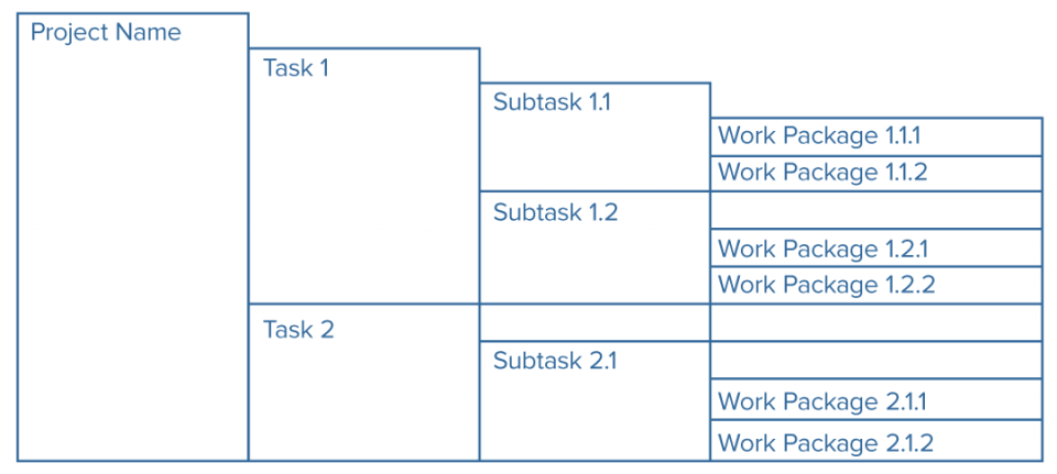
The complete piece of work breakdown structure is the basis of the project schedule, which tells you when each task should start and terminate in guild for the building to be ready on fourth dimension. To arrive at the schedule, construction planners determine task durations and establish the precedence relationships between tasks.
Task durations are the lengths of time required to complete each task, and are determined by a number of factors. Some of these factors are controllable (for example, the number of personnel or the type and availability of equipment needed to complete a chore) and some are uncontrollable (the fact that cement must dry for several hours before the next process tin happen, regardless of the resources available). Experienced builders guess task durations based on how long it took them to do similar tasks in prior projects. Often, planners volition use statistical techniques, such every bit program evaluation and review technique (PERT) to approximate the fourth dimension required to complete a chore.
Precedence relationships are the logical order in which you will complete tasks. A combination of basic chore logic — figuring out what must happen before, during, and after performing a specific chore — and physical or practical constraints determine precedence relationships. Builders have an intuitive understanding of task logic: Y'all have to lay the bricks before you tin paint the walls.
Other constraints that can exist hard to see in accelerate may affect task execution. For example, it may announced that the cabinetry team and the painting team can work simultaneously, except that the space is likewise small for all the workers.
Once you lot determine chore durations and precedence relationships, you can create a precedence network. A precedence network is a visual representation of all project tasks that you conform in logical order. Nodes, or hollow circles, represent activities that contain written task durations, and arrows betwixt nodes represent the club in which you perform tasks.
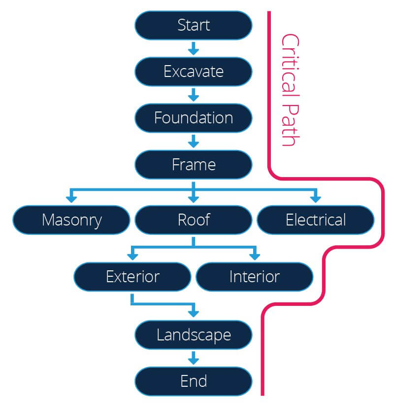
The precedence network drives scheduling with a technique called the disquisitional path method (CPM). The CPM establishes the early and late commencement and stop dates for tasks — that is, when you can (or must) kickoff and finish them in social club to complete the project on time. Information technology besides identifies the project's critical path, a sequence of activities for which whatsoever filibuster will push back the projection's completion date.
Since all of these activities follow from the work breakdown structure, you can clearly run into the importance of construction plans to the planning and scheduling of a edifice projection.
Construction Drawings Aid Planners Make Key Building Decisions
Blueprints too shape other important decisions, such as the option of technology and construction methods for a project. Builders appraise the calibration not only of the project as a whole, simply also of specific components of the project, such as building materials and their position within the construction. This process allows contractors and construction planners to figure out what kind of equipment and structure techniques they'll use.
For example, a structure planner might inquire whether a project requires a cement mixer truck or just a bike-based cement mixer. And, once the crew mixes the cement, practise they need to pump the mixture to the college levels of the structure, or can they transfer information technology by pulley or even manually?
Blueprints likewise make information technology piece of cake to check if the structure conforms with edifice rules and codes and if it'south set for building departments to result permits for new and renovated structures. Most jurisdictions have building departments or councils that must issue permits for new construction or renovation projects earlier the construction work tin begin.
For instance, inspectors will cheque whether buildings take adequate fire protection and safely positioned windows, include enough parking, and many other details. Project owners seeking a edifice permit communicate these details by submitting the blueprints for review. Authorities allow departments will pore over the plans and check for compliance with building rules and codes before giving construction the permission to break basis.
Programme Specifications and the Construction Estimating Process
Earlier, we touched on specifications and how they're different from structure plans. Builders use a standardized coding system, such as MasterFormat, to simplify specifications and make it piece of cake for all participants to communicate requirements. MasterFormat, developed by the U.S. Construction Specifications Found (CSI) and Structure Specifications of Canada, comprises fifty major divisions of construction data for commercial and institutional projects.
In this coding arrangement, you place each work production with a serial of numbers that describes the major category and subcategory, and the blazon of work involved. For instance, masonry is in division 04, and the dirt unit masonry is in subgroup 21. Brick masonry gets MasterFormat number 04 21 13, which you would employ on the construction plan.
Construction plans assist builders estimate costs, especially during the early stages of a projection when contractors are preparing bids. To arrive at a price approximate, you use a technique called quantity takeoff and prepare a document called the bill of quantities.
The quantity takeoff calculates the materials you need in a structure project. Its proper noun derives from the expression "taking off," and it lists material quantities from the construction drawings and specifications. Y'all list, for example, how much wood you crave for an activity, so you lot multiply that amount by how many times that activity occurs during construction.
The quantity takeoff is a adequately specialized operation performed by an estimator who can both read blueprints and quantify all costs for piece of work tasks without overlooking anything or double counting. Pinpointing costs is tricky - even for someone who can read blueprints - because architects vary in how conspicuously they enumerate all dimensions on structure plans. A cost estimator or quantity surveyor typically performs the quantity takeoff.
Use this quantity takeoff worksheet to become a sense of the process.

Download Quantity Takeoff Worksheet for Structure
Excel | Word | PDF
The neb of quantities lists the material quantities from the quantity takeoff, and contractors use this to decide their expenses on materials and labor for the project. This adding enables them to bid accurately. The nib looks like an extensive table of itemized costs: The scope of each particular is described in some detail and accompanied by the number of units of each particular (in terms of area, length, volume, or other dimensions equally advisable), the price per unit, and the resulting total price of that item. The bill of quantities also includes so-chosen contingency costs for unforeseen expenditures and waste costs and materials prone to breakage or wastage. Since the bill of quantities is an exhaustive document, you only prepare it in one case yous have a completed and finalized set of structure plans.
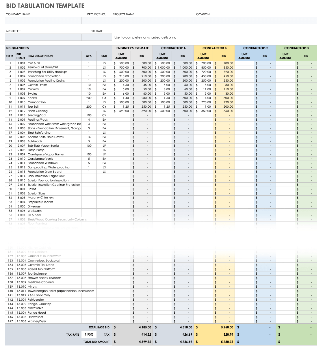
Download Bid Tabulation Template
Excel | Smartsheet
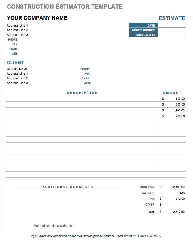
Download Construction Estimator Template
Excel | Smartsheet
Working with Construction Plans
Paper structure plans are large (well-nigh 24 by 36 inches) and consist of several pages. To start working with these documents, you'll first need to clear a workspace where you can fully unfold the plans. Also, recollect that newspaper plans tear and fade hands, and they deteriorate if they go wet. They're very expensive to produce and toll hundreds of dollars to supercede, and so make sure you're using them and storing them carefully.
Y'all can easily experience overwhelmed by the sheer size and amount of detail on the plans, so the first stride in working with them is to relax. Unlike books, plans practise not have a single starting identify. Focus your attention on one corner, and and then work your mode across. Good plans show a lot of detail and are highly accurate.
Next, figure out what kind of programme you lot're looking at: Is the perspective bird'southward middle or side on? Is this a total view or a section? If it'due south a section, which expanse does information technology pertain to?
Adjacent, cheque the calibration. The scale is the ratio between a construction component's dimensions on the cartoon and its bodily dimensions. Architects utilise scales with fractions, such as one/8 inch equals ane foot, while engineers use whole-integer scales, such as 1 inch equals 100 anxiety. You use architectural scales in plans for buildings, and engineering scales in plans for other construction projects, such as roads or dams. This guide from the U.S. Burn down Administration is a practiced primer on how to select the right scale and accurately interpret the dimensions.
If the architect possesses written dimensions for the plan, utilise those instead of measuring the dimensions with a ruler. According to a U.S. Navy design reading and sketching course, newspaper will stretch or shrink over time, which tin can make dimensions bigger or smaller than you intended.
You might also come across amended plans with written dimensions that don't stand for to those suggested by the scale. Sometimes, in the revision process, y'all miss details. Cross reference the dimensions you computed using a ruler and pattern scales with those you've detailed explicitly on the drawing to see whether they concord. Also, attempt comparing different plans with elevations to see whether the dimensions add up. If you are measuring dimensions using the ruler and scale, remember to bank check whether someone reduced the drawings themselves during reproduction.
Since scaled dimensions aren't always authentic, an architect, engineer, or contractor should never rely on construction plan scales to calculate dimensions. Instead, use the dimensions written explicitly on the plans - if these are unavailable, contact the architect to obtain missing dimensions.
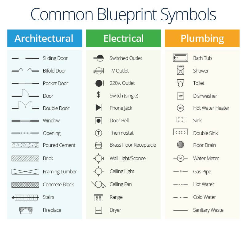
Construction plans feature symbols that represent components of the completed structure. For complex projects, architects may employ hundreds of abbreviations and symbols. These represent all the structural components, down to ix unlike symbols for ix different types of doors. The symbols are mostly standardized, but architects have latitude to use their own symbols. Either style, the programme will feature a key explaining what the symbols mean. In improver, the builder volition depict elements, like stonework, using simple graphics. If you want to brush up on pattern symbols before you go your hands on a set up of plans, check out these complimentary resources that HousePlanHelper.com offers.
On your programme, you'll notice several different types of lines. These lines indicate everything from the visible and invisible sides of objects to the dimensions and centre axes of objects. Figure 1-3 in this Regular army Carpentry Field Manual details all the types of lines you'll run across in architectural drawings as well every bit what they mean.
The Full general Order of Drawings in a Set of Construction Plans
A set of plans for a single residential project tin include dozens of separate drawings (in some cases, at that place might be more than 100). In that location's no standard practice for how many drawings a fix of plans will include: It depends on the project, the architect's preferred level of detail, and the customs of the builder'due south part. Speedily browse the entire prepare of plans earlier you start, so you know what the builder has included.
The topmost sheet is the cover sheet. Information technology includes the appointment, the name and location of the projection, and the architect's proper noun, address, and contact information. The encompass sheet may also feature an architect'south rendering of the completed structure.
In many states, applying for a construction allow requires an architect or engineer to stamp the drawings. Stamped plans bear the seal of a registered and licensed engineer or architect. The professional applies the seal with an ink postage stamp that shows the person'south proper noun, country, license number, credential, and expiration engagement for their license.
After the cover canvas comes a plan index, which lists all the drawings contained in the gear up. It also contains a list of commonly used abbreviations, a scale bar that indicates the plan scale, and pattern notes if needed.
Typically, the architect volition identify each cartoon with a letter of the alphabet and number. The letter denotes the plan series: A for architectural plans, S for structural applied science plans, Due east for electrical plans, Thou for mechanical plans, and P for plumbing plans. The number refers to a specific plan blazon. (For example, A2 plans are site plans, A3 plans are flooring plans, and A5 plans are roof plans.) If the construction has multiple levels, the designer will add additional numbers. Each architectural business firm uses their own plan-numbering conventions.
The typical order of drawings subsequently the cover sheet and programme alphabetize is as follows:
- Thou for General Sheets: Cover sheet, plan index, and location plans
- A for Site and Architectural Plans: Floor plans, ceiling plans, roof plans, elevations, sections, wall sections, and others, depending on the architect's chosen level of detail
- S for Structural Engineering: Framing plans for foundations, floors, and roofs
- E, Grand, and P for Electrical, Mechanical, and Plumbing Components (though small residential plans may non feature these)
- Finish Schedule and the Door and Window Schedule: Door, window, and other interior types and finishes
- Specifications: Detailed descriptions of the materials (though these may also be appended to the A-serial architectural plans)
The level of detail (LOD) is proportional to the number of plans in the set and determined by the architect on a project-past-project footing. The builder is responsible for making sure the construction's occupants and users are safe, so they generally choose to include more than particular rather than less. There'southward also a growing trend for architects to include more details to make information technology easier for contractors during bidding and structure. If the builder repeats a particular or dimension on multiple floors, they may note that it is "typical at all floors" instead of detailing it on each drawing. Information technology is the contractor's responsibility to make certain they include these repeated details in their estimates.
Each cartoon will also feature a championship block in the lower-right corner, which lists the proper name of the specific drawing, the drawing number, the proper name of the party who prepared the drawing, the date, the record of approval, and the scale. Architects may create their drawings on gridded sheets to brand pinpointing the location of various construction components easier if people are viewing the sheets simultaneously from remote locations.
If you've revised a drawing, you'll as well include a revision block (usually in the acme-right corner of the drawing but sometimes as part of the title block). Check the revision cake to brand sure you're looking at the latest approved drawing. A numbered bubble indicates a revision on a drawing. In a corner of the drawing, you provide a record of revision dates and descriptions with corresponding numbers, usually in easily recognizable shapes, such as a triangle or octagon. If you make revisions, a proficient practice is to insert the new sheet in front of the sheet you're changing. You tin can fold the erstwhile canvas in on itself and tape it closed. Marker the sheet number "void."
You'll also hear references to two other types of drawings: redline drawings and as-congenital drawings. Redline drawings, so named because you lot draw them in blood-red over the original structure plans, betoken where the actual constructed structure differs from the original program and typically indicate only minor changes. As-built drawings contain the changes from redline drawings, in effect making them official and depicting the terminal structure every bit built.
No set of drawings is e'er perfect, and there will be discrepancies between dissimilar plans that feature the same structural components. To shift responsibleness for these discrepancies onto the builder, the builder will typically specify that the contractor follow the highest standard of quantity or quality in case of alien data.
Additional Plans for Steel Construction
The construction plans for a steel structure will typically characteristic other drawings in addition to the full general plans, which depict the main members of the steel structure, particular their size and material, and testify their position relative to each other.
Fabrication drawings item the size, shape, and material for each member of the construction equally well equally the means in which each member connects or attaches to other members. You lot use the fabrication drawings to procure the required materials for construction.
Erection drawings show the placement of members in the final structure, and normally item their weights. You pattern these mainly to aid fieldwork.
Falsework drawings bear witness any supportive structures that you volition demand to temporarily erect effectually the main structure.
Structure Plans for Different Building Parts
Permit's delve into each plan blazon in detail. For a look at the construction plans for a typical residential project, check out what the business firm Donald A. Gardner Architects provides in one of its house plan sets.
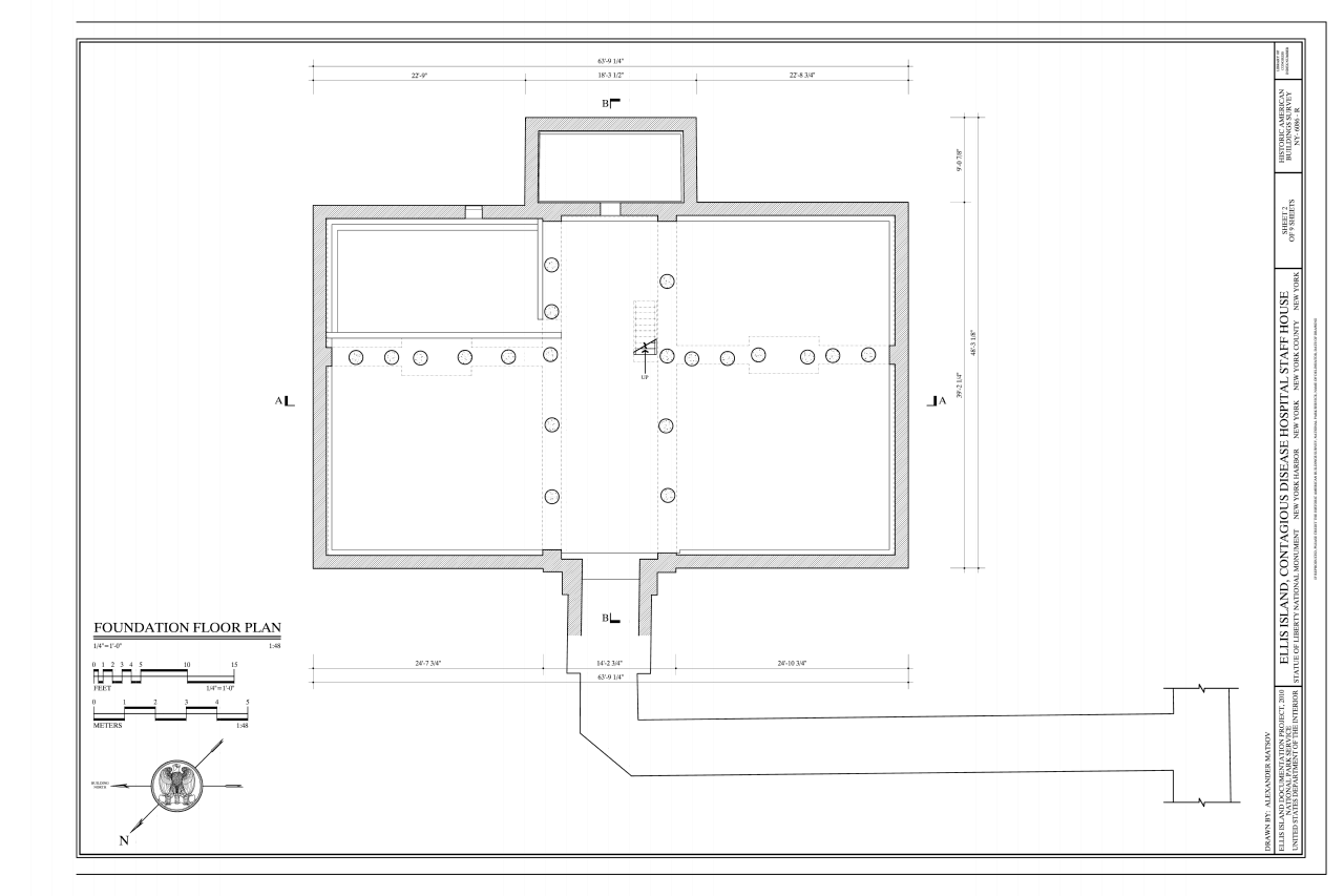
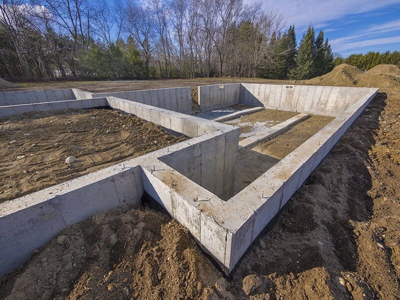
Foundation plans are a type of structural engineering plan. They tin can also refer to subfloor plans or, in some cases, basement floor plans. They show the sizes, shapes, thicknesses, configurations, and elevations of foundation walls and footings, including interior load-begetting walls and outside mail service footings. Foundation plans will also show the positioning of reinforcing confined and the connections and attachments via anchor bolts or weld plates betwixt the foundation's structural members. These plans delineate excavated and unexcavated areas of the foundation.
A footing schedule accompanies the foundation plan. It lists and describes all the footings upon which the structure will rest. Typically, there volition be all-encompassing notes that explain how you reinforce structural members and define the physical break strength requirements. The notes volition also describe how you test the strength of the construction.
Framing plans are another type of structural technology programme. They detail the structural members that constitute the building's framework: the size and positions of beams that appear in plans, and the joist and rafter space, layout, and size. Framing plans assist builders lay out roof, floor, and ceiling structures.
A framing plan for a roof volition prove the various elements of the roof's structure, including dormers, hips, valleys, drains, and any equipment mounted on the roof. It also shows the roof pitch. Pre-engineered flooring and roof systems are also bachelor. If you use these, the manufacturer must provide engineering information to the builders, and building inspectors will probably want to review the program earlier issuing a permit.
Floor plans are architectural plans that show the layout of each level of the structure. The drafter shows the layout from an overhead perspective that omits the roof and any upper floors. The floor plans illustrate the configuration of internal walls, doors, windows, and wall insets, such as fireplaces and chimneys. They also indicate the placement of permanent fixtures, such as bathrooms, major appliances, and internal structures (stairways or elevators).
Each floor will have a flooring programme that includes a description of the intended uses of rooms or other internal spaces. The designer will indicate both door and window sizes and requite dimensions, including lengths, widths, and internal foursquare footages. Homeowners tend to be most interested in the floor plan, equally it'due south perchance the most straightforward and modifiable of all construction documents. The flooring plan also makes information technology like shooting fish in a barrel to moving-picture show how foot traffic will menses and how people volition use the infinite.
1 uncommon variation of the floor plan is the ceiling plan, which is a view of the ceiling as seen from beneath. Ceiling plans are only used for structures that have significant ceiling fixtures (and so typically non residential projects).
Elevations are side views of a edifice that may show either the exterior or the interior and omit external walls. Exterior elevations prove the placement of doors and windows, the external finish of the building, including any masonry or other decorative elements, and a side view of the roofing. They may also indicate the natural gradient of the footing around the base of the building. Interior elevations show the height and placement of cabinets, countertops, and detailing, such equally tiles on bathroom walls.
Elevations communicate peak, a dimension that bird'due south-center views can't display effectively. Elevations also betoken the direction that an superlative faces, as the management of sunshine and wind patterns is of import when deciding how to place buildings, especially houses.
You should cross-reference elevations with floor plans. Many people assume the architect will include an elevation for every exterior wall, but this is not always truthful. Compare the floor plans to the elevations to make sure you haven't missed annihilation.
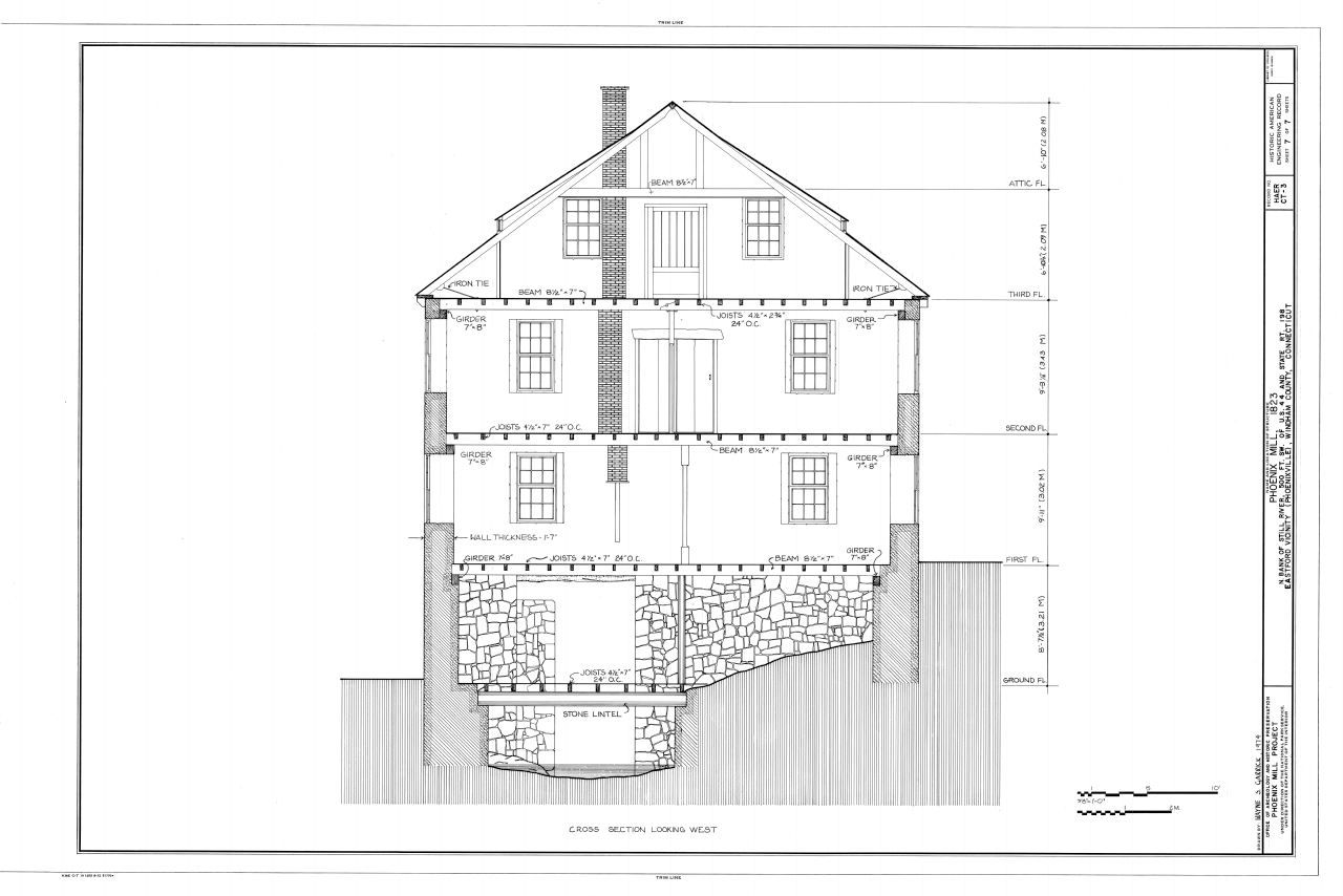
Cantankerous sections are also a kind of side view, but these represent a vertical slice through the building to show all internal components. A cross section details both visible components, such as stairs, sidings, and covering, and concealed components, such as framing members, headers, and insulation. A cross section can pass through whatsoever level of the house, from the roof to the footings. Information technology captures things like cabinets and countertops, and too internal framing components (this is important because bird'southward-eye views tin't draw them effectively). One common type of cross section is a wall cross section that shows both the inside and exterior faces of walls equally well as internal components, such equally studs and insulation.
Where a simple residential projection might only require a few cross sections, a more complicated commercial structure might need many more, since in that location are many variations in the components that become behind walls. Y'all will cantankerous-reference cantankerous sections on programme views and elevations.
Site plans locate a building in the wider context of the land or parcel. They detail the general dimensions and location of the site with reference to neighboring lots and their boundaries, and as well marker the building's footprint on the site, and identify site landscaping features,roads, and pavements. Ultimately, the site plan summarizes work you will complete on site.
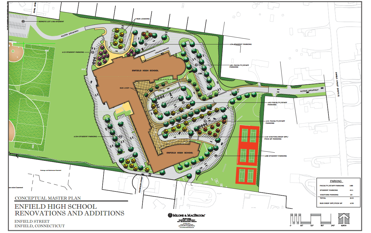
The site plan locates existing infrastructure that y'all demand to protect during construction, such as sewer lines and utilities connections. Information technology contains information on the course and peak of the structure site. These plans show the location of structures that are non function of the building proper, such as drainage systems and roads. Building inspectors considering whether to laurels a construction permit volition check whether parking volition accommodate the new construction's occupants.
Mechanical plans, like floor plans, are overhead views. They feature the mechanical components of a construction, such as HVAC, gas lines, and plumbing. Putting these details on a split sail prevents conventional plans from becoming too crowded and hard to read. Non all structure projects will accept separate mechanical plans - yous usually merely create them for projects with circuitous mechanical systems.
Mechanical plans will depict both the visible and concealed components of mechanical systems — both ventilators and ducts for a HVAC system, for case. These plans may also show any appliances connected to a mechanical arrangement, such as gas ovens. When examining mechanical plans with multiple extensive systems, recall that infinite restrictions may mean that subcontractors have to work in series, not simultaneously.
Environmental plans accost how the project will manage erosion and sedimentation of waters well-nigh the construction site. Given the amount of earth displaced and moved during structure, they're designed to ensure that all that soil doesn't end up polluting and blocking nearby waterways. Environmental plans also include procedures for minimizing constitute removal and dealing with chemical spills.
The environmental plan typically lists a serial of best management practices (BMPs) designed to minimize the harmful impact on the environment. In many jurisdictions, an environmental plan is a requirement to continue with structure.
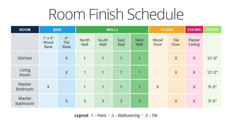
Schedules feature all the details an architect doesn't want to squeeze into a floor plan. A schedule is a simple matrix of edifice component data, where each entry corresponds to a number that likewise appears on the floor plan. Schedule information is highly detailed: A door schedule, for instance, will feature data on doors, door frames, and locks. A finish schedule is a comprehensive table of finishes (paint, flooring, etc.) in each room. Windows and light fixtures will also appear on schedules.
Schedules will likewise include items labeled OFCI (possessor-furnished, contractor-installed), GFCI (government-furnished, contractor-installed), NIC (non in contract), and by others (those items provided exterior the scope of a item trade or contractor). In full general, the schedule volition besides show commitment dates for items that yous have ordered.
To learn more about blueprints and how to read them, check out this course by Construction Experts Inc. The book Pattern Reading: Structure Drawings for the Building Trades likewise covers the topic, and Francis D.Grand. Ching'south Building Construction Illustrated is a helpful reference. Print Reading for Construction, by Walter Brown and Daniel Dorfmueller, is some other resources.
How to Lay out a Building Footprint from Blueprints
Interested in learning exactly where a structure will lie on a lot? You'll accept to lay out the edifice'south "footprint," which is the surface area of land it occupies at ground level. Being able to practice this, or at least empathise it very clearly, is a cadre slice of construction knowledge.
To start, look at the site plan to find reference points that will allow you to locate the structure. If the site plan doesn't make reference to existing landmarks or features of the landscape, chances are information technology uses a coordinate system comprising northings and eastings to locate the edifice. You'll likewise need to apply an instrument called a total station theodolite (TST) to determine the building's coordinates. Call back, the smaller the lot and the closer it is to other structures, the greater the need for precision when locating the building'due south coordinates. Start by locating the corners of one side of the building, and measure distances to landmarks to make sure you've positioned the corners correctly. Work your way around until you've located all the corners.
Your side by side step is filling in the lines between corners. There are a number of ways to do this, depending on the type of structure that you intend to build: You lot might measure and locate cavalcade lines, foundation lines, or outside wall lines. An architect or architect can tell y'all which is most appropriate, and y'all'll need to learn how the different line types appear on the site plan. Use a triangle-blazon rule to scale distances on plans, every bit they're less likely to upshot in measuring errors. If you need to add distances, employ a architect's calculator, which volition expedite mathematical operations based on dimensions. CAD plans also help make up one's mind distances, particularly within the exterior building line (OBL).
Edifice work typically needs to first on level surfaces, so y'all'll also demand to establish the peak, if any, from which work will embark. The tiptop is computed with reference to nearby structures or to body of water level (check out the Australian Top Datum). The site plan will indicate a measurement called the "summit above the existing grade," or will utilise an existing vertical mark to show the elevation.
Structure Safety Plans Can Save Lives
So far, nosotros've talked virtually construction plans specifically as documents that provide technical information well-nigh a construction and how to build it. These plans include blueprints, specifications, and schedules. Just construction plans also refers to the results of the broader planning procedure that encompasses environmental, rubber, and quality plans.
Safety plans are important because structure is hazardous, and the best fashion to preclude an accident is to anticipate what could go wrong. In 2015, according to the Occupational Condom and Health Administration (OSHA), one in five private-industry worker fatalities — a total of 937 deaths — occurred in the construction industry. Nearly one in 10 U.S. structure workers will sustain injuries in any given year. Falls cause the most injuries.
Prophylactic planning isn't every bit rigorous in small-scale residential projects, but it is a regulatory requirement for large projects. OSHA standard 29 CFR 1926, "Safety and Health Regulations for Construction," defines construction project safe standards, and OSHA has 10 construction safe program requirements for the construction industry.
Safety planning revolves around risk reduction and hazard elimination to avoid on-site accidents. It's most constructive when integrated proactively with project planning so that information technology evolves with site and environmental conditions.
Safety planning is an integral part of construction design and scheduling. Builders who identify potential hazards for construction crews — a practice called job take a chance analysis — can proactively mitigate them by implementing safety measures and emergency response equipment. This extends from observing occupancy limits for bars spaces to making burn down condom equipment available close to where it might exist needed. These risk-control steps, along with plans for what to do if an accident occurs, are the projection's rubber management strategies.
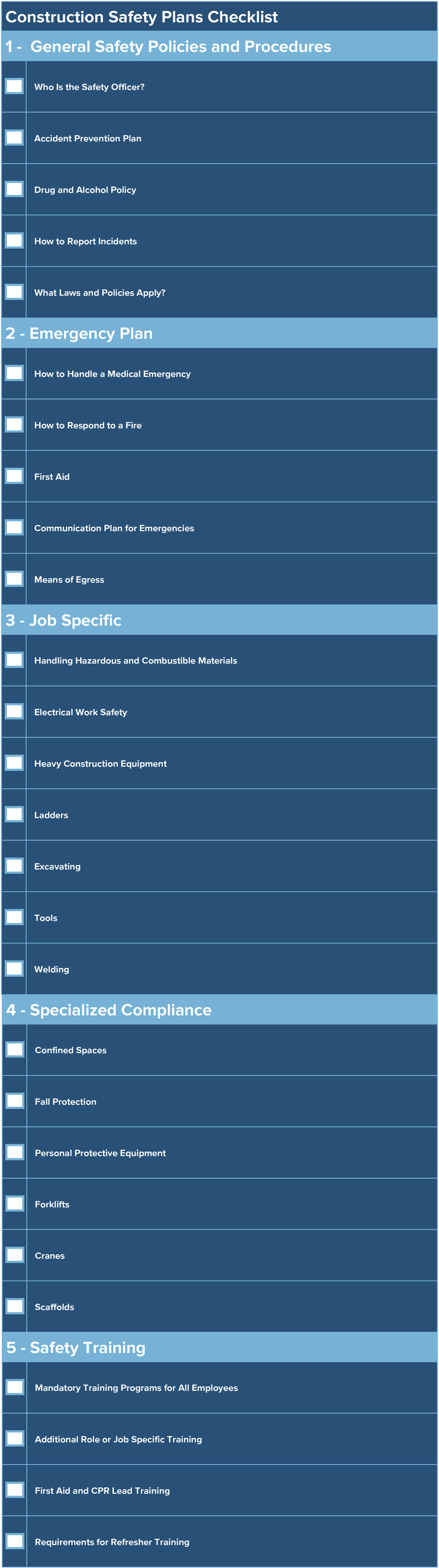
If you need to compile or evaluate a construction program, information technology helps to know the traditional elements. Review OSHA's rubber checklist for structure. A construction safety plan must include certain sections and answer central questions, such every bit who is in accuse of condom on site, what arrangements be for medical treatment, what safety training you will conduct, and the lockout/tagout procedures.
Use the checklist beneath as a starting point for your site safety plan. Nevertheless, remember that your final safety plan needs to be specific to the hazards present in your unique circumstances. Follow all applicative regulations, such as OSHA requirements.
Download Construction Condom Plans Checklist
Quality Plans Help Builders Thrill Clients and Users
A construction quality plan is a document that explains how a contractor will see the quality requirements for a specific project. It'south not the same as a visitor's general quality policies, since information technology addresses quality management for an individual project.
Whether formally required in a contract or informally requested, the quality programme is an of import part of the customer-contractor working relationship. For the customer, information technology improves conviction in the contractor's ability to get the job done and builds in a machinery for accountability. For the contractor, it ensures all parties are on the aforementioned page and that the projection outcome will enhance their reputation.
The quality plan for a project identifies those responsible for quality direction and establishes protocols for quality-related communications. It highlights the regulations and industry standards that utilise to a project, and explains procedures for assessing quality. Lastly, it explains how subcontractors comply with the plan and the quality requirements for materials procurement.
Ed Caldeira of First Fourth dimension Quality explains what a skilful quality direction plan will tell a client:
- "Who is in charge of quality direction on the project, and what are their qualifications?
- How and when will yous communicate quality-related bug to the contractor's personnel and the customer?
- What sort of quality oversight arrangement will you put in place?
- How will yous ensure quality from subcontractors and suppliers?
- What constitutes satisfactory quality for a project? What quality standards will you fix?
- How volition y'all test quality?
- Should they arise, how volition you fix quality issues?
- How volition you assess the projection'due south deliverables quality?"
When developing a quality control program for construction, consider covering the following topics:
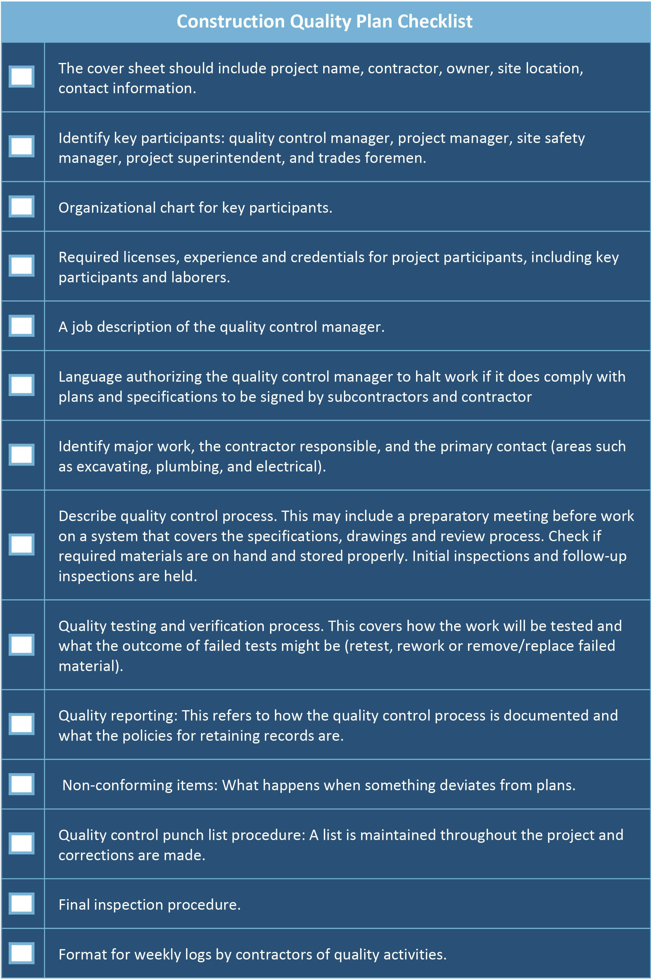
Download Structure Quality Plans Checklist
Technology Eases Construction Planning
Earlier we talked most the difficulty of working with blueprints. Construction has lagged behind other major industries in digital adoption, and planning technology solves many of the problems and constraints of conventional paper construction plans.
Construction planning applied science covers a number of software solutions, from scheduling apps to SaaS suites. The pattern modules reduce the fourth dimension and money costs of manually updating construction plans and reworking design elements.
The most helpful features include the following abilities:
- View, edit, and share drawings
- Access plans and documents in the field from mobile devices
- Zoom in with high-resolution plans to capture detail
- Ensure sheet version command
- Store in the cloud
- Think plans quickly with fast-loading optimization
- Comment with markups and as-congenital notes
- Take photos and share and archive them
- Automate quantity takeoff
These capabilities unlock some strong advantages for builders and project managers. With these tools, collaboration flows more than easily, everyone always has the electric current set of plans, accuracy rises, and all participants (whether they are in the part or the field) share the same information. Scheduling engines requite contractors a competitive reward past increasing productivity. Quality also rises since project teams can update and share blueprints, dial lists, specifications, and RFIs instantaneously.
These capabilities increase efficiency. One construction software company surveyed its customers, who said that on average they saved $15,000 in labor per twelvemonth per employee by using a construction solution.
That financial do good accrues from greater efficiency. But not using paper plans also saves on printing costs. Aside from architect fees, plans typically cost $ii to $iv a page to impress. The documents sets for large commercial projects volition have hundreds of pages, and many project managers, supervisors, and foremen need their own set. You'll also have to reprint sheets when in that location are changes, and since changes are mutual, the costs rapidly add upward. Of class, using digital plans ways team members must accept tablets or laptops and a subscription to an application that more often than not has a fee.
These tools would not be without other technological innovations in the structure programme earth, such as CAD and building data modeling (BIM). CAD was the precursor to BIM: It began as the groundbreaking apply of software to design physical components, specially in manufacturing, though civil engineering projects used it besides. Designers and so embraced it for drawing plans.
BIM is the next stage in construction design. It goes beyond ii-dimensional CAD to 3D edifice information models that offer comprehensive data for entire construction projects. BIM provides highly complex digital representations of building blueprint, and it'south stretching across 3D visualization to so-called 4D and 5D integration of time and cost information.
CAD made it easy to view, edit, and share construction drawings, with no perceptible loss of quality. CAD plans also make dimensions easier to measure. These drawings mimic some of the strengths of traditional paper plans merely are easier to share and mark up.
Glossary of Key Terms in Structure Plans
Beneath, you lot'll find a useful list of terms concerning structure plans.
- Edifice Envelope: The consummate set of physical structures that separate a building's interior from its exterior, such as walls, roofs, and floors.
- Civil Drawing: A type of site plan designed for utilise by civil engineers that shows topographical features, landscaping, and utility connections.
- Eastings: A prepare of east-extending coordinates on a geographic plane. Together with northings, they establish a system of Cartesian coordinates that yous use to plot building locations with reference to already existing landmarks. See as well northings.
- Footing: A component of a building's foundation that transfers the weight you place on walls to the footing. Compared to other types of foundations, footings are typically quite shallow, though there are restrictions on minimum footing depth.
- GFCI (Government-Furnished, Contractor-Installed): This acronym, used on structure plans and specifications, indicates materials or components that the project owner will procure — in this case, the project owner is the regime, and they provide the GFCI to the contractor for installation. The GFCI mark on construction plans tells toll estimators which work items they practice non need to procure. It's also a reminder for the contractor to coordinate a delivery schedule with the government.
- Level of Detail and Level of Evolution: We frequently refer to both of these terms as LOD. Level of item describes the increasing amount of detail in graphical representation as construction plans become more refined. A conceptual cartoon is much less detailed than a detailed cartoon. Level of development describes how much development and applied science have gone into the characteristic.
- NIC (Not in Contract): This acronym, used on construction plans and specifications, indicates work items that are not the main contractor's responsibility to deliver. The project owner either delivers these piece of work items or contracts with some other political party to have them deliver the items. The NIC mark on construction plans tells price estimators which piece of work items they should not bid for.
- Northings: A ready of northward-extending coordinates on a geographic plane. Together with eastings, they constitute a system of Cartesian coordinates that you use to plot edifice locations with reference to already existing landmarks. See also eastings.
- OFCI (Owner-Furnished, Contractor-Installed): This acronym, which you use on construction plans and specifications, indicates materials or components that the project possessor will procure and provide to the contractor for installation. The OFCI mark on structure plans tells toll estimators which work items they do non need to procure. It's also a reminder for the contractor to coordinate a delivery schedule with the owner.
- Exterior Building Line: A unremarkably used reference bespeak in construction drawings that helps planners decide distances to other structural components.
- Quantity Takeoff: A technique for estimating the types and quantities of materials and labor required to complete a construction projection. The quantity takeoff is role of the project cost estimating process. It gets its name from the way toll estimators would originally perform the part, when they would "take off" quantities of all materials from blueprints and specifications to prepare an itemized list.
Improve Construction Plans with Smartsheet for Structure
From pre-construction to projection closeout, go along all stakeholders in the loop with real-fourth dimension collaboration and automatic updates and then you lot can brand better, more than informed decisions, all while landing your projects on fourth dimension and within budget.
The Smartsheet platform makes information technology easy to plan, capture, manage, and written report on work from anywhere, helping your team be more effective and get more than washed. Study on primal metrics and get real-time visibility into work as information technology happens with roll-up reports, dashboards, and automated workflows built to keep your team connected and informed.
When teams have clarity into the work getting done, there's no telling how much more they tin can accomplish in the aforementioned amount of time. Try Smartsheet for free, today.
Source: https://www.smartsheet.com/how-to-read-construction-plans
0 Response to "Residential Construction Plans Usually Contain What Drawings"
Post a Comment